about filter

choco
Thu, 03/08/2012 - 02:48 am
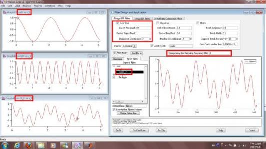
First,I made three wave cos3t , cos13t and cos13_3t . (The cos13_3t is cos3t +cos13t.)
Then, I made an figure (cos13_3t vs. x_1 , x_1 is x*0.01) and used the "filter" to filter the high frequency data. (cos13t)
My method in the figure,I don't know why I am failed.
Another problem is
1. What is a design frequency?
2. Does the raw data to be dealt with need to has its own finite intrinsic/characteristic frequency?
Or can it be any data with no obvious periodic feature?
(And the only periodic feature imposed on it is the noise we want to filter out.)


Use the wave scaling to set the sampling frequency of the signal (100 Hz in your example)
Now when you select one of these waves to filter, the design frequency (which is the same as the sampling frequency when you choose a wave to be filtered), will be properly set to 100Hz.
Click the Filter dialog's "Help" button to read about the Digital Signal Processing (DSP) terminology such as "design frequency" or "sampling frequency".
An FIR filter with only 3 coefficients isn't going to do very much filtering (a lowpass filter won't reject much), and your test signals have almost all of their energy at very low frequencies, as an FFT of those waves will show.
You also might want to review some basic DSP definitions:
http://www.dspguru.com/dsp/faqs/fir
--Jim Prouty
Software Engineer, WaveMetrics, Inc.
March 8, 2012 at 04:09 pm - Permalink